Commensurate line circuit

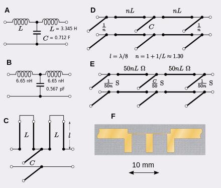
Commensurate line circuits are electrical circuits composed of transmission lines that are all the same length; commonly one-eighth of a wavelength. Lumped element circuits can be directly converted to distributed element circuits of this form by the use of Richards' transformation. This transformation has a particularly simple result; inductors are replaced with transmission lines terminated in short-circuits and capacitors are replaced with lines terminated in open-circuits. Commensurate line theory is particularly useful for designing distributed element filters for use at microwave frequencies.
It is usually necessary to carry out a further transformation of the circuit using Kuroda's identities. There are several reasons for applying one of the Kuroda transformations; the principal reason is usually to eliminate series connected components. In some technologies, including the widely used microstrip, series connections are difficult or impossible to implement.
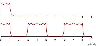
The frequency response of commensurate line circuits, like all distributed element circuits, will periodically repeat, limiting the frequency range over which they are effective. Circuits designed by the methods of Richards and Kuroda are not the most compact. Refinements to the methods of coupling elements together can produce more compact designs. Nevertheless, the commensurate line theory remains the basis for many of these more advanced filter designs.
Commensurate lines
Commensurate lines are transmission lines that are all the same electrical length, but not necessarily the same characteristic impedance (Z0). A commensurate line circuit is an electrical circuit composed only of commensurate lines terminated with resistors or short- and open-circuits. In 1948, Paul I. Richards published a theory of commensurate line circuits by which a passive lumped element circuit could be transformed into a distributed element circuit with precisely the same characteristics over a certain frequency range.[1]
Lengths of lines in distributed element circuits, for generality, are usually expressed in terms of the circuit's nominal operational wavelength, λ. Lines of the prescribed length in a commensurate line circuit are called unit elements (UEs). A particularly simple relationship pertains if the UEs are λ/8.[2] Each element in the lumped circuit is transformed into a corresponding UE. However, Z0 of the lines must be set according to the component value in the analogous lumped circuit and this may result in values of Z0 that are not practical to implement. This is particularly a problem with printed technologies, such as microstrip, when implementing high characteristic impedances. High impedance requires narrow lines and there is a minimum size that can be printed. Very wide lines, on the other hand, allow the possibility of undesirable transverse resonant modes to form. A different length of UE, with a different Z0, may be chosen to overcome these problems.[3]
Electrical length can also be expressed as the phase change between the start and the end of the line. Phase is measured in angle units. , the mathematical symbol for an angle variable, is used as the symbol for electrical length when expressed as an angle. In this convention λ represents 360°, or 2π radians.[4]
The advantage of using commensurate lines is that the commensurate line theory allows circuits to be synthesised from a prescribed frequency function. While any circuit using arbitrary transmission line lengths can be analysed to determine its frequency function, that circuit cannot necessarily be easily synthesised starting from the frequency function. The fundamental problem is that using more than one length generally requires more than one frequency variable. Using commensurate lines requires only one frequency variable. A well developed theory exists for synthesising lumped element circuits from a given frequency function. Any circuit so synthesised can be converted to a commensurate line circuit using Richards' transformation and a new frequency variable.[5]
Richards' transformation
Richards' transformation transforms the angular frequency variable, ω, according to,
or, more usefully for further analysis, in terms of the complex frequency variable, s,
- where k is an arbitrary constant related to the UE length, θ, and some designer chosen reference frequency, ωc, by
- k has units of time and is, in fact, the phase delay inserted by a UE.
Comparing this transform with expressions for the driving point impedance of stubs terminated, respectively, with a short circuit and an open circuit,
it can be seen that (for θ < π/2) a short circuit stub has the impedance of a lumped inductance and an open circuit stub has the impedance of a lumped capacitance. Richards' transformation substitutes inductors with short circuited UEs and capacitors with open circuited UEs.[6]
When the length is λ/8 (or θ=π/4), this simplifies to,
This is frequently written as,
L and C are conventionally the symbols for inductance and capacitance, but here they represent respectively the characteristic impedance of an inductive stub and the characteristic admittance of a capacitive stub. This convention is used by numerous authors, and later in this article.[7]
Omega-domain

Richards' transformation can be viewed as transforming from a s-domain representation to a new domain called the Ω-domain where,
If Ω is normalised so that Ω=1 when ω=ωc, then it is required that,
and the length in distance units becomes,
Any circuit composed of discrete, linear, lumped components will have a transfer function H(s) that is a rational function in s. A circuit composed of transmission line UEs derived from the lumped circuit by Richards' transformation will have a transfer function H(jΩ) that is a rational function of precisely the same form as H(s). That is, the shape of the frequency response of the lumped circuit against the s frequency variable will be precisely the same as the shape of the frequency response of the transmission line circuit against the jΩ frequency variable and the circuit will be functionally the same.[8]
However, infinity in the Ω domain is transformed to ω=π/4k in the s domain. The entire frequency response is squeezed down to this finite interval. Above this frequency, the same response is repeated in the same intervals, alternately in reverse. This is a consequence of the periodic nature of the tangent function. This multiple passband result is a general feature of all distributed element circuits, not just those arrived at through Richards' transformation.[9]
Cascade element
A UE connected in cascade is a two-port network that has no exactly corresponding circuit in lumped elements. It is functionally a fixed delay. There are lumped-element circuits that can approximate a fixed delay such as the Bessel filter, but they only work within a prescribed passband, even with ideal components. Alternatively, lumped-element all-pass filters can be constructed that pass all frequencies (with ideal components), but they have constant delay only within a narrow band of frequencies. Examples are the lattice phase equaliser and bridged T delay equaliser.[10]
There is consequently no lumped circuit that Richard's transformation can transform into a cascade-connected line, and there is no reverse transformation for this element. Commensurate line theory thus introduces a new element of delay, or length.[1] Two or more UEs connected in cascade with the same Z0 are equivalent to a single, longer, transmission line. Thus, lines of length nθ for integer n are allowable in commensurate circuits. Some circuits can be implemented entirely as a cascade of UEs: impedance matching networks, for instance, can be done this way, as can most filters.[1]
Kuroda's identities

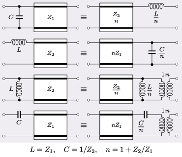
Kuroda's identities are a set of four equivalent circuits that overcome certain difficulties with applying Richards' transformations directly. The four basic transformations are shown in the figure. Here the symbols for capacitors and inductors are used to represent open-circuit and short-circuit stubs. Likewise, the symbols C and L here represent respectively the susceptance of an open circuit stub and the reactance of a short circuit stub, which, for θ=λ/8, are respectively equal to the characteristic admittance and characteristic impedance of the stub line. The boxes with thick lines represent cascade connected commensurate lengths of line with the marked characteristic impedance.[11]
The first difficulty solved is that all the UEs are required to be connected together at the same point. This arises because the lumped element model assumes that all the elements take up zero space (or no significant space) and that there is no delay in signals between the elements. Applying Richards' transformation to convert the lumped circuit into a distributed circuit allows the element to now occupy a finite space (its length) but does not remove the requirement for zero distance between the interconnections. By repeatedly applying the first two Kuroda identities, UE lengths of the lines feeding into the ports of the circuit can be moved between the circuit components to physically separate them.[12]
A second difficulty that Kuroda's identities can overcome is that series connected lines are not always practical. While series connection of lines can easily be done in, for instance, coaxial technology, it is not possible in the widely used microstrip technology and other planar technologies. Filter circuits frequently use a ladder topology with alternating series and shunt elements. Such circuits can be converted to all shunt components in the same step used to space the components with the first two identities.[13]
The third and fourth identities allow characteristic impedances to be scaled down or up respectively. These can be useful for transforming impedances that are impractical to implement. However, they have the disadvantage of requiring the addition of an ideal transformer with a turns ratio equal to the scaling factor.[14]
History
In the decade after Richards' publication, advances in the theory of distributed circuits took place mostly in Japan. K. Kuroda published these identities in 1955 in his Ph.D thesis.[15] However, they did not appear in English until 1958 in a paper by Ozaki and Ishii on stripline filters.[16]
Further refinements
One of the major applications of commensurate line theory is to design distributed element filters. Such filters constructed directly by Richards' and Kuroda's method are not very compact. This can be an important design consideration, especially in mobile devices. The stubs stick out to the side of the main line and the space between them is not doing anything useful. Ideally, the stubs should project on alternate sides[17] to prevent them coupling with each other, taking up further space, although this is not always done for space considerations. More than that, the cascade connected elements that couple together the stubs contribute nothing to the frequency function, they are only there to transform the stubs into the required impedance. Putting it another way, the order of the frequency function is determined solely by the number of stubs, not by the total number of UEs (generally speaking, the higher the order, the better the filter). More complex synthesis techniques can produce filters in which all elements are contributing.[16]
The cascade connected λ/8 sections of the Kuroda circuits are an example of impedance transformers, the archetypical example of such circuits is the λ/4 impedance transformer. Although this is double the length of the λ/8 line it has the useful property that it can be transformed from a low-pass filter to a high-pass filter by replacing the open circuit stubs with short circuit stubs. The two filters are exactly matched with the same cut-off frequency and mirror-symmetrical responses. It is therefore ideal for use in diplexers.[18] The λ/4 transformer has this property of being invariant under a low-pass to high-pass transformation because it is not just an impedance transformer, but a special case of transformer, an impedance inverter. That is, it transforms any impedance network at one port, to the inverse impedance, or dual impedance, at the other port. However, a single length of transmission line can only be precisely λ/4 long at its resonant frequency and there is consequently a limit to the bandwidth over which it will work. There are more complex kinds of inverter circuit that more accurately invert impedances. There are two classes of inverter, the J-inverter, which transforms a shunt admittance into a series impedance, and the K-inverter which does the reverse transformation. The coefficients J and K are respectively the scaling admittance and impedance of the converter.[19]
Stubs may be lengthened in order to change from an open circuit to a short circuit stub and vice versa.[20] Low-pass filters usually consist of series inductors and shunt capacitors. Applying Kuroda's identities will convert these to all shunt capacitors, which are open circuit stubs. Open circuit stubs are preferred in printed technologies because they are easier to implement, and this is the technology likely to be found in consumer products. However, this is not the case in other technologies such as coaxial line, or twin-lead where the short circuit may actually be helpful for mechanical support of the structure. Short circuits also have a small advantage in that they are generally have a more precise position than open circuits. If the circuit is to be further transformed into the waveguide medium then open circuits are out of the question because there would be radiation out of the aperture so formed. For a high-pass filter the inverse applies, applying Kuroda will naturally result in short circuit stubs and it may be desirable for a printed design to convert to open circuits. As an example, a λ/8 open circuit stub can be replaced with a 3λ/8 short circuit stub of the same characteristic impedance without changing the circuit functionally.[21]
Coupling elements together with impedance transformer lines is not the most compact design. Other methods of coupling have been developed, especially for band-pass filters that are far more compact. These include parallel lines filters, interdigital filters, hairpin filters, and the semi-lumped design combline filters.[22]
References
- 1 2 3 Levy & Cohn, p. 1056
- ↑ Kumar & Grebennikov, p. 116
- Wen, p. 256
- ↑ Gardner & Wickert, p. 70
- ↑ Weik, p. 270
- ↑ Hunter, p. 137
- ↑ Richards, pp. 217–218
- Levy & Cohn, p. 1056
- Hunter, p. 139
- ↑ See for instance;
- Levy & Cohn, p. 1058
- Kumar & Grebennikov, p. 118
- Bhat & Koul, p. 583
- ↑ Besser & Gilmore, p. 457
- Hunter, p. 140
- ↑ Hunter, p. 140
- ↑ Helszajn, p. 124
- ↑ Levy & Cohn, p. 1058
- Kumar & Grebennikov, p. 118
- Sisodia, p. 5.27
- ↑ Levy & Cohn, p. 1057
- Sisodia, p. 5.27
- ↑ Besser & Gilmore, p. 469
- Sisodia, p. 5.27
- ↑ Sisodia, p. 5.27
- ↑ Wen, p. 256
- 1 2 Levy & Cohn, p. 1057
- ↑ Lee, p. 789
- ↑ Levy & Cohn, p. 1059
- ↑ Du & Swamy, p. 403
- ↑ Matthaei et al., pp. 605–614
- ↑ Poole & Darwazeh, pp. 315–316
- ↑ Levy & Cohn, p. 1058
- Maloratsky, pp. 219–234
Bibliography
- Besser, Les; Gilmore, Rowan, Practical RF Circuit Design for Modern Wireless Systems: Volume 1: Passive Circuits and Systems, Artech House, 2002 ISBN 1580536751.
- Bhat, Bharathi; Koul, Shiban K., Stripline-like Transmission Lines for Microwave Integrated Circuits, New Age International, 1989 ISBN 8122400523.
- Du, Ke-Lin; Swamy, M. N. S., Wireless Communication Systems, Cambridge University Press, 2010 ISBN 1139485768.
- Gardner, Mark A.; Wickert, David W., "Microwave filter design using radial line stubs", 1988 IEEE Region 5 Conference: Spanning the Peaks of Electrotechnology, p. 68-72, IEEE, March 1988.
- Helszajn, Joseph, Synthesis of Lumped Element, Distributed and Planar Filters, McGraw-Hill, 1990 ISBN 0077071662.
- Hunter, Ian C., Theory and Design of Microwave Filters, IET, 2001 ISBN 0852967772.
- Kumar, Narendra; Grebennikov, Andrei; Distributed Power Amplifiers for RF and Microwave Communications, Artech House, 2015 ISBN 1608078329.
- Lee, Thomas H., Planar Microwave Engineering, vol. 1, Cambridge University Press, 2004 ISBN 0521835267.
- Levy, Ralph; Cohn, Seymour B., "A History of Microwave Filter Research, Design, and Development", IEEE Transactions on Microwave Theory and Techniques, vol. 32, iss. 9, pp. 1055–1067, September 1984.
- Maloratsky, Leo, Passive RF & Microwave Integrated Circuits, Elsevier, 2003 ISBN 0080492053.
- Matthaei, George L.; Young, Leo; Jones, E. M. T. Microwave Filters, Impedance-Matching Networks, and Coupling Structures McGraw-Hill 1964 OCLC 282667.
- Ozaki, H.; Ishii, J., "Synthesis of a class of strip-line filters", IRE Transactions on Circuit Theory, vol. 5, iss. 2, pp. 104–109. June 1958.
- Richards, Paul I., "Resistor-transmission-line circuits", Proceedings of the IRE, vol. 36, iss. 2, pp. 217–220, 1948.
- Sisodia, M. L., Microwaves: Introduction To Circuits,Devices And Antennas, New Age International, 2007 ISBN 8122413382.
- Wen, Geyi, Foundations for Radio Frequency Engineering, World Scientific, 2015 ISBN 981457872X.
- Wiek, Martin, Fiber Optics Standard Dictionary, Springer, 1997 ISBN 0412122413.