Lift (force)
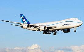
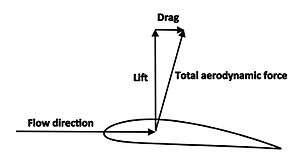
A fluid flowing past the surface of a body exerts a force on it. Lift is the component of this force that is perpendicular to the oncoming flow direction.[1] It contrasts with the drag force, which is the component of the surface force parallel to the flow direction. If the fluid is air, the force is called an aerodynamic force. In water, it is called a hydrodynamic force.
Overview
Lift is most commonly associated with the wing of a fixed-wing aircraft, although lift is also generated by propellers, kites, helicopter rotors, rudders, sails and keels on sailboats, hydrofoils, wings on auto racing cars, wind turbines, and other streamlined objects. Lift is also exploited in the animal world, and even in the plant world by the seeds of certain trees.[2] While the common meaning of the word "lift" assumes that lift opposes weight, lift in the technical sense used in this article can be in any direction with respect to gravity, since it is defined with respect to the direction of flow rather than to the direction of gravity. When an aircraft is flying straight and level (cruise) most of the lift opposes gravity.[3] However, when an aircraft is climbing, descending, or banking in a turn the lift is tilted with respect to the vertical.[4] Lift may also be entirely downwards in some aerobatic manoeuvres, or on the wing on a racing car. In this last case, the term downforce is often used. Lift may also be largely horizontal, for instance on a sail on a sailboat.
Aerodynamic lift is distinguished from other kinds of lift in fluids. Aerodynamic lift requires relative motion of the fluid which distinguishes it from aerostatic lift or buoyancy lift as used by balloons, blimps, and dirigibles. Aerodynamic lift usually refers to situations in which the body is completely immersed in the fluid, and is thus distinguished from planing lift as used by motorboats, surfboards, and water-skis, in which only a lower portion of the body is immersed in the lifting fluid flow.
Simplified physical explanations of lift on an airfoil

An airfoil is a streamlined shape that is capable of generating significantly more lift than drag.[5] A flat plate can generate lift, but not as much as a streamlined airfoil, and with somewhat higher drag.
There are several ways to explain how an airfoil generates lift. Some are more complicated or more mathematically rigorous than others; some have been shown to be incorrect.[6][7][8][9][10] For example, there are explanations based directly on Newton’s laws of motion and explanations based on Bernoulli’s principle. Either can be used to explain lift.[11][12]
Flow deflection and Newton's laws
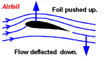
An airfoil generates lift by exerting a downward force on the air as it flows past. According to Newton's third law, the air must exert an equal and opposite (upward) force on the airfoil, which is the lift.[13][14][15][16]
The air flow changes direction as it passes the airfoil and follows a path that is curved downward. According to Newton's second law, this change in flow direction requires a downward force applied to the air by the airfoil. Then, according to Newton's third law, the air must exert an upward force on the airfoil. The overall result is that a reaction force, the lift, is generated opposite to the directional change. In the case of an airplane wing, the wing exerts a downward force on the air and the air exerts an upward force on the wing.[17][18][19][20][21][22][23][24]
The downward turning of the flow is not produced solely by the lower surface of the airfoil, and the air flow above the foil accounts for much of the downward-turning action.
This simple application of Newton's laws does not provide a complete theory of lift. In particular, it does not explain how the downforce on the air arises.[26]
Increased flow speed and Bernoulli's principle
Bernoulli's principle states that within a steady airflow of constant energy, when the air flows through a region of lower pressure it speeds up and vice versa.[27] Thus, there is a direct mathematical relationship between the pressure and the speed, so if one knows the speed at all points within the airflow one can calculate the pressure, and vice versa. For any airfoil generating lift, there must be a pressure imbalance, i.e. lower average air pressure on the top than on the bottom. Bernoulli's principle states that this pressure difference must be accompanied by a speed difference.
Conservation of mass

Starting with the flow pattern observed in both theory and experiments, the increased flow speed over the upper surface can be explained in terms of streamtube pinching and conservation of mass.[25]
The streamlines divide the flow around the airfoil into streamtubes as depicted by the spaces between the streamlines in the adjacent diagram. By definition, fluid never crosses a streamline in a steady flow. Assuming that the air is incompressible, the rate of volume flow (e.g. liters or gallons per minute) must be constant within each streamtube since matter is not created or destroyed. If a streamtube becomes narrower, the flow speed must increase in the narrower region to maintain the constant flow rate. This is an application of the principle of conservation of mass.[28]
The picture shows that the upper stream tubes constrict as they flow up and around the airfoil. Conservation of mass says that the flow speed must increase as the stream tube area decreases.[25] Similarly, the lower stream tubes expand and the flow slows down.
From Bernoulli's principle, the pressure on the upper surface where the flow is moving faster is lower than the pressure on the lower surface where it is moving slower. This pressure difference creates a net aerodynamic force, pointing upward.
Limitations of explanations based on Bernoulli's principle
- The explanation above does not explain why the streamtubes change size. To see why the air flows the way it does requires more sophisticated analysis.[29][30][31]
- Sometimes a geometrical argument is offered to demonstrate why the streamtubes change size: it is asserted that the top "obstructs" or "constricts" the air more than the bottom, hence narrower streamtubes. For conventional wings that are flat on the bottom and curved on top this makes some intuitive sense. But it does not explain how flat plates, symmetric airfoils, sailboat sails, or conventional airfoils flying upside down can generate lift, and attempts to calculate lift based on the amount of constriction do not predict experimental results.[32][33][34][35]
- A common explanation using Bernoulli's principle asserts that the air must traverse both the top and bottom in the same amount of time and that this explains the increased speed on the (longer) top side of the wing. But this assertion is false; it is typically the case that the air parcels traveling over the upper surface will reach the trailing edge before those traveling over the bottom.[36]
Basic attributes of lift
Lift is a result of pressure differences and depends on angle of attack, airfoil shape, air density, and airspeed.
Pressure differences
Pressure is the normal force per unit area exerted by the air on itself and on surfaces that it touches. The lift force is transmitted through the pressure, which acts perpendicular to the surface of the airfoil. The air maintains physical contact at all points. Thus, the net force manifests itself as pressure differences. The direction of the net force implies that the average pressure on the upper surface of the airfoil is lower than the average pressure on the underside.[37]
These pressure differences arise in conjunction with the curved air flow. Whenever a fluid follows a curved path, there is a pressure gradient perpendicular to the flow direction with higher pressure on the outside of the curve and lower pressure on the inside.[38] This direct relationship between curved streamlines and pressure differences was derived from Newton's second law by Leonhard Euler in 1754:
The left hand side of this equation represents the pressure difference perpendicular to the fluid flow. On the right hand side ρ is the density, v is the velocity, and R is the radius of curvature. This formula shows that higher velocities and tighter curvatures create larger pressure differentials and that for straight flow (R → ∞) the pressure difference is zero.[39]
Angle of attack

The angle of attack is the angle between the chord line of an airfoil and the oncoming air. A symmetrical airfoil will generate zero lift at zero angle of attack. But as the angle of attack increases, the air is deflected through a larger angle and the vertical component of the airstream velocity increases, resulting in more lift. For small angles a symmetrical airfoil will generate a lift force roughly proportional to the angle of attack.[40][41]
As the angle of attack grows larger, the lift reaches a maximum at some angle; increasing the angle of attack beyond this critical angle of attack causes the upper-surface flow to separate from the wing; there is less deflection downward so the airfoil generates less lift. The airfoil is said to be stalled.[42]
Airfoil shape
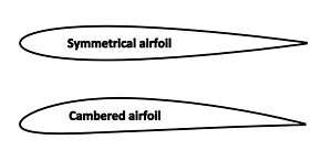
The lift force depends on the shape of the airfoil, especially the amount of camber (curvature such that the upper surface is more convex than the lower surface, as illustrated at right). Increasing the camber generally increases lift.[43][44]
Cambered airfoils will generate lift at zero angle of attack. When the chord line is horizontal, the trailing edge has a downward direction and since the air follows the trailing edge it is deflected downward.[45] When a cambered airfoil is upside down, the angle of attack can be adjusted so that the lift force is upwards. This explains how a plane can fly upside down.[46][47]
The wings of birds and most subsonic aircraft have spans much larger than their chords. For wings of this general shape (often referred to as having a high aspect-ratio), the most important features of the lifting flow can be explained in terms of the two-dimensional flow around an airfoil, which is just the shape of a cross-section of the wing, as illustrated in the drawing at right.[48] Most of the discussion in this article concentrates on two-dimensional airfoil flow. However, the flow around a three-dimensional wing involves significant additional issues, and these are discussed below under Lift of three dimensional wings. For a wing of low aspect ratio, such as a delta wing, two-dimensional airfoil flow is not relevant, and three-dimensional flow effects dominate.[49]
Air speed and density
The flow conditions also affect lift. Lift is proportional to the density of the air and approximately proportional to the square of the flow speed. Lift also depends on the size of the wing, being generally proportional to the wing's area projected in the lift direction. In aerodynamic theory and engineering calculations it is often convenient to quantify lift in terms of a "Lift coefficient" defined in a way that makes use of these proportionalities.
Lift coefficient
If the lift coefficient for a wing at a specified angle of attack is known (or estimated using a method such as thin airfoil theory), then the lift produced for specific flow conditions can be determined using the following equation:[50]
where
- L is lift force,
- ρ is air density,
- v is true airspeed,
- A is the wing area, and
- is the lift coefficient at the desired angle of attack, Mach number, and Reynolds number[51]
Pressure integration
When the pressure distribution on the airfoil surface is known, determining the total lift requires adding up the contributions to the pressure force from local elements of the surface, each with its own local value of pressure. The total lift is thus the integral of the pressure, in the direction perpendicular to the farfield flow, over the entire surface of the airfoil or wing.[52]
where:
- L is the lift,
- A is the wing surface area
- p is the value of the pressure,
- n is the normal unit vector pointing into the wing, and
- k is the vertical unit vector, normal to the freestream direction.
The above lift equation neglects the skin friction forces, which typically have a negligible contribution to the lift compared to the pressure forces. By using the streamwise vector i parallel to the freestream in place of k in the integral, we obtain an expression for the pressure drag Dp (which includes the pressure portion of the profile drag and, if the wing is three-dimensional, the induced drag). If we use the spanwise vector j, we obtain the side force Y.
The validity of this integration generally requires the airfoil shape to be a closed curve that is piecewise smooth.
A more comprehensive physical explanation
As described above, there are two main popular explanations of lift, one based on downward deflection of the flow combined with Newton's laws, and one based on changes in flow speed combined with Bernoulli's principle. Either of these, by itself, correctly identifies some aspects of the lifting flow but leaves other important aspects of the phenomenon unexplained. A more comprehensive explanation involves both downward deflection and changes in flow speed, and requires looking at the flow in more detail.[53]
Lift involves action and reaction at the airfoil surface and is felt as a pressure difference
The airfoil shape and angle of attack work together so that the airfoil exerts a downward force on the air as it flows past. According to Newton's third law, the air must then exert an equal and opposite (upward) force on the airfoil, which is the lift.[14][15]
The force is exerted by the air as a pressure difference on the airfoil's surfaces.[54] Pressure in a fluid is always positive in an absolute sense,[55] so that pressure must always be thought of as pushing, and never as pulling. The pressure thus pushes inward on the airfoil everywhere on both the upper and lower surfaces. The flowing air reacts to the presence of the wing by reducing the pressure on the wing's upper surface and increasing the pressure on the lower surface. The pressure on the lower surface pushes up harder than the reduced pressure on the upper surface pushes down, and the net result is upward lift.[54]
The pressure difference that exerts lift acts directly on the airfoil surfaces. But understanding how the pressure difference is produced requires understanding what the flow does over a wider area.
The airfoil affects the flow over a wide area around it
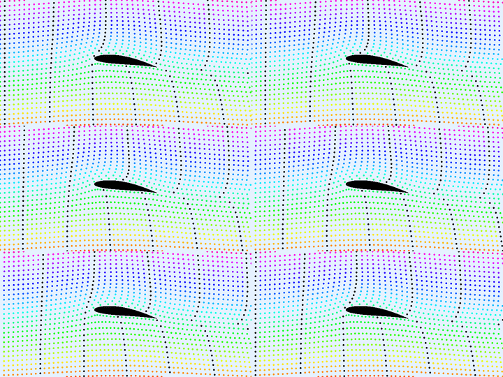
An airfoil affects the speed and direction of the flow over a wide area. When an airfoil produces lift, the flow ahead of the airfoil is deflected upward, the flow above and below the airfoil is deflected downward, and the flow behind the airfoil is deflected upward again, leaving the air far behind the airfoil flowing in the same direction as the oncoming flow far ahead. The flow above the upper surface is always speeded up, and the flow below the airfoil is usually slowed down. The downward deflection and the changes in flow speed are pronounced and extend over a wide area, as can be seen in the flow animation on the right. These differences in the direction and speed of the flow are greatest close to the airfoil and decrease gradually far above and below. All of these features of the velocity field also appear in theoretical models for lifting flows.[56][57]
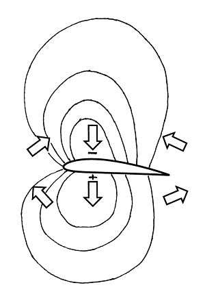
The pressure is also affected over a wide area. When an airfoil produces lift, there is always a diffuse region of low pressure above the airfoil, and there is usually a diffuse region of high pressure below, as illustrated by the isobars (curves of constant pressure) in the drawing. The pressure difference that acts on the surface is just part of this spread-out pattern of non-uniform pressure.[53]
The pressure differences and the changes in flow speed and direction support each other in a mutual interaction
The non-uniform pressure exerts forces on the air in the direction from higher pressure to lower pressure. The direction of the force is different at different locations around the airfoil, as indicated by the block arrows in the pressure distribution with isobars figure. Air above the airfoil is pushed toward the center of the low-pressure region, and air below the airfoil is pushed outward from the center of the high-pressure region.
According to Newton's second law, a force causes air to accelerate in the direction of the force. Thus the vertical arrows in the pressure distribution with isobars figure indicate that air above and below the airfoil is accelerated, or turned, downward, and that the non-uniform pressure is thus the cause of the downward deflection of the flow visible in the flow animation. To produce this downward turning, the airfoil must have a positive angle of attack or have its rear portion curved downward as on an airfoil with camber. Note that the downward turning of the flow over the upper surface is the result of the air being pushed downward by higher pressure above it than below it.
The arrows ahead of the airfoil indicate that the flow ahead of the airfoil is deflected upward, and the arrows behind the airfoil indicate that the flow behind is deflected upward again, after being deflected downward over the airfoil. These defections are also visible in the flow animation.
The arrows ahead of the airfoil and behind also indicate that air passing through the low-pressure region above the airfoil is speeded up as it enters, and slowed back down as it leaves. Air passing through the high-pressure region below the airfoil sees the opposite: It is slowed down and then speeded back up. Thus the non-uniform pressure is also the cause of the changes in flow speed visible in the flow animation. The changes in flow speed are consistent with Bernoulli's principle, which states that in a steady flow without viscosity, lower pressure means higher speed, and higher pressure means lower speed.
Thus changes in flow direction and speed are directly caused by the non-uniform pressure. But this cause-and-effect relationship is not just one-way; it works in both directions simultaneously. The air's motion is affected by the pressure differences, but the existence of the pressure differences depends on the air's motion. The relationship is thus a mutual, or reciprocal, interaction: Air flow changes speed or direction in response to pressure differences, and the pressure differences are sustained by the air's resistance to changing speed or direction.[58] A pressure difference can exist only if something is there for it to push against. In the case of an aerodynamic flow, what a pressure difference pushes against is the inertia of the air, as the air is accelerated by the pressure difference.[53] And this is why the mass of the air is important, and why lift depends on air density.
In summary, sustaining the pressure difference that exerts the lift force on the airfoil surfaces requires sustaining a pattern of non-uniform pressure spread over a wide area around the airfoil. This requires maintaining pressure differences in both the vertical and horizontal directions, and thus requires both downward turning of the flow and changes in flow speed according to Bernoulli's principle. The pressure differences and the changes in flow direction and speed sustain each other in a mutual interaction. The pressure differences follow naturally from Newton's second law and from the fact that the flow along the surface naturally follows the predominantly downward-sloping contours of the airfoil. And the fact that the air has mass is crucial to the interaction.[53]
The understanding of lift as a physical phenomenon
The scientific understanding of lift is based on mathematical theories of continuum fluid mechanics[59][60][61] that are in turn based on established principles of physics, as discussed below under "Mathematical theories of lift". The applications of these theories to aerodynamic flows have been agreed upon by the scientific and engineering communities since the early 20th century.[62][63] Starting with just the shape of the lifting surface and the general flow conditions (airspeed, density, and angle of attack), the existence of lift, the amount of lift, and all of the important details of the lifting flow have been predicted successfully by the theories. Thus lift can be considered to be thoroughly understood in a scientific sense. Furthermore, the quantitative theories provide useful quantitative information for engineering purposes.
Simplified physical explanations of lift, without mathematics, are also useful for purposes of understanding, especially by non-technical audiences. These qualitative explanations are by their nature less rigorous and are thus not as well established as the mathematical theories, and they cannot provide quantitative information for engineering. A difficulty in devising such explanations is finding a satisfactory balance between completeness on one hand, and simplicity and brevity on the other. Fluid flows in general are complex phenomena, and simplified explanations are seldom completely satisfactory. Many different explanations of lift have been proposed, reflecting different choices of what aspect of the flow to emphasize. In many cases, oversimplification has led to incompleteness and/or outright errors.[6][8][9][10] There has been a long history of disagreement and controversy, even into recent years, but only regarding the qualitative explanations, not the science itself.[64][65][66]
Mathematical theories of lift
The mathematical theories are based on continuum fluid mechanics, in which it is assumed that air flows as if it were a continuous fluid. Lift is generated in accordance with the fundamental principles of physics, the most relevant being the following three principles:[67]
- Conservation of momentum, which is a direct consequence of Newton's laws of motion, especially Newton's second law which relates the net force on an element of air to its rate of momentum change,
- Conservation of Mass, including the common assumption that the airfoil's surface is impermeable for the air flowing around, and
- Conservation of energy, which says that energy is neither created nor destroyed.
Because an airfoil affects the flow in a wide area around it, these physical principles must be enforced at all points throughout an extended region. To do this requires expressing the conservation principles in the form of partial-differential equations combined with a set of boundary conditions (requirements the flow has to satisfy at the airfoil surface and far away from the airfoil).[68]
To predict lift requires solving the equations for a particular airfoil shape and flow condition, which generally requires calculations that are so voluminous that they are practical only on a computer, through the methods of Computational Fluid Dynamics (CFD). Determining the net aerodynamic pressure from a CFD solution requires "adding up" (integrating) the pressures determined by the CFD over the surface of the airfoil as described under "Pressure integration".
The Navier-Stokes equations (NS) provide the potentially most accurate theory of lift, but in practice, capturing the effects of turbulence in the boundary layer on the airfoil surface requires sacrificing some accuracy and using the Reynolds-Averaged Navier-Stokes equations (RANS), as explained below. Simpler but less accurate theories have also been developed and are described below.
Navier-Stokes (NS) equations
These equations represent conservation of mass, Newton's second law (conservation of momentum), conservation of energy, the Newtonian law for the action of viscosity, the Fourier heat conduction law, an equation of state relating density, temperature, and pressure, and formulas for the viscosity and thermal conductivity of the fluid.[69] [70]
In principle, the NS equations, combined with boundary conditions of no through-flow and no slip at the airfoil surface, could be used to predict lift in any situation in ordinary atmospheric flight with high accuracy. However, lifting flows in practical situations always involve turbulence in the boundary layer next to the airfoil surface, at least over the aft portion of the airfoil. Predicting lift by solving the NS equations in their raw form would require the calculations to resolve the details of the turbulence, down to the smallest eddy. This is not yet possible, even on the most powerful current computer.[71] So in principle the NS equations provide a complete and very accurate theory of lift, but practical prediction of lift requires that the effects of turbulence be modeled in the RANS equations rather than computed directly.
Reynolds-Averaged Navier-Stokes (RANS) equations
These are the NS equations with the turbulence motions averaged over time, and the effects of the turbulence on the time-averaged flow represented by turbulence modeling (an additional set of equations based on a combination of dimensional analysis and empirical information on how turbulence affects a boundary layer in a time-averaged average sense).[72][73] A RANS solution consists of the time-averaged velocity vector, pressure, density, and temperature defined at a dense grid of points surrounding the airfoil.
The amount of computation required is a minuscule fraction (billionths)[71] of what would be required to resolve all of the turbulence motions in a raw NS calculation, and with large computers available it is now practical to carry out RANS calculations for complete airplanes in three dimensions. Because turbulence models are not perfect, the accuracy of RANS calculations is imperfect, but it is good enough to be very helpful to airplane designers. Lift predicted by RANS is usually within a few percent of the actual lift.
Inviscid-flow equations (Euler or potential)
The Euler equations are the NS equations with the viscosity, heat conduction, and turbulence effects deleted.[74] As with a RANS solution, an Euler solution consists of the velocity vector, pressure, density, and temperature defined at a dense grid of points surrounding the airfoil. While the Euler equations are simpler than the NS equations, they still do not lend themselves to exact analytic solutions. Further simplification is available through potential flow theory, which reduces the number of unknowns that must be solved for and makes analytic solutions possible in some cases, as described below.
Either Euler or potential-flow calculations predict the pressure distribution on the airfoil surfaces roughly correctly for angles of attack below stall, where they might miss the total lift by as much as 10-20%. At angles of attack above stall, inviscid calculations do not predict that stall has happened, and as a result they grossly overestimate the lift.
In potential-flow theory, the flow is assumed to be irrotational, i.e. that small fluid parcels have no net rate of rotation. Mathematically, this is expressed by the statement that the curl of the velocity vector field is everywhere equal to zero. Irrotational flows have the convenient property that the velocity can be expressed as the gradient of a scalar function called a potential. A flow represented in this way is called potential flow.[75][76][77][78]
In potential-flow theory, the flow is usually further assumed to be incompressible. Incompressible potential-flow theory has the advantage that the equation (Laplace's equation) to be solved for the potential is linear, which allows solutions to be constructed by superposition of other known solutions. The incompressible-potential-flow equation can also be solved by conformal mapping, a method based on the theory of functions of a complex variable. In the early 20th century, before computers were available, conformal mapping was used to generate solutions to the incompressible potential-flow equation for a class of idealized airfoil shapes, providing some of the first practical theoretical predictions of the pressure distribution on a lifting airfoil.
A solution of the potential equation directly determines only the velocity field. The pressure field is deduced from the velocity field through Bernoulli's equation.
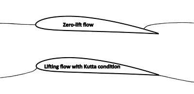
Applying potential-flow theory to a lifting flow requires special treatment and an additional assumption. The problem arises because lift on an airfoil in inviscid flow requires circulation in the flow around the airfoil (See "Circulation and the Kutta-Joukowski theorem" below), but a single potential function that is continuous throughout the domain around the airfoil cannot represent a flow with nonzero circulation. The solution to this problem is to introduce a branch cut, a curve or line from some point on the airfoil surface out to infinite distance, and to allow a jump in the value of the potential across the cut. The jump in the potential imposes circulation in the flow equal to the potential jump and thus allows nonzero circulation to be represented. However, the potential jump is a free parameter that is not determined by the potential equation or the other boundary conditions, and the solution is thus indeterminate. A potential-flow solution exists for any value of the circulation and any value of the lift. One way to resolve this indeterminacy is to impose the Kutta condition,[79][80] which is that, of all the possible solutions, the physically reasonable solution is the one in which the flow leaves the trailing edge smoothly. The streamline sketches illustrate one flow pattern with zero lift, in which the flow goes around the trailing edge and leaves the upper surface ahead of the trailing edge, and another flow pattern with positive lift, in which the flow leaves smoothly at the trailing edge in accordance with the Kutta condition.
Linearized potential flow
This is potential-flow theory with the further assumptions that the airfoil is very thin and the angle of attack is small.[81] The linearized theory predicts the general character of the airfoil pressure distribution and how it is influenced by airfoil shape and angle of attack, but is not accurate enough for design work. For a 2D airfoil, such calculations can be done in a fraction of a second in a spreadsheet on a PC.
Circulation and the Kutta-Joukowski theorem
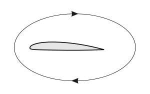
The Kutta-Joukowski theorem relates the lift on an airfoil to a circulatory component (circulation) of the flow around the airfoil.[56][82][83] Kutta-Joukowski is not a complete theory of lift in the same sense as those listed above because it does not predict how much circulation or lift a given airfoil will produce. Calculating the lift from Kutta-Joukowski requires a known value for the circulation.
The circulation is the contour integral of the tangential velocity of the air on a closed loop (also called a 'circuit') around the boundary of an airfoil. It can be understood as the total amount of "spinning" (or vorticity) of air around the airfoil. The section lift/span can be calculated using the Kutta–Joukowski theorem:[18]
where is the air density, is the free-stream airspeed.
Several components of the overall velocity field contribute to the circulation: the upward flow ahead of the airfoil, the accelerated flow above the airfoil, the decelerated flow below the airfoil, and the downward flow behind the airfoil. One derivation of the Kutta-Joukowski theorem involves integrating the fluxes of vertical momentum ahead of the airfoil and behind (on vertical planes extending to large distances above and below), taking the difference, and showing that the result is related to both the lift and the circulation. The flux of upward momentum ahead of the airfoil is found to account for half the lift, and the flux of downward momentum behind the airfoil is found to account for the other half, a result that also applies to three-dimensional wings.[56][82][83]
The Kutta-Joukowski theorem is a key element in an explanation of lift that follows the development of the flow around an airfoil as the airfoil starts its motion from rest and a starting vortex is formed and left behind, leading to the formation of circulation around the airfoil.[84][85][86] Lift is then inferred from the Kutta-Joukowski theorem. This explanation is largely mathematical, and its general progression is based on logical inference, not physical cause-and-effect.[87]
The circulation around a conventional airfoil, and hence the lift it generates, is dictated by both its design and the flight conditions, such as forward velocity and angle of attack. Lift can be increased by artificially increasing the circulation, for example by boundary-layer blowing or the use of blown flaps. In the Flettner rotor the entire airfoil is circular and spins about a spanwise axis to create the circulation.
Momentum balance in lifting flows
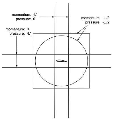
The flow around a lifting airfoil must satisfy Newton's second law, or conservation of momentum, both locally at every point in the flow field, and in an integrated sense over any extended region of the flow. For an extended region, Newton's second law takes the form of the momentum theorem for a control volume, where a control volume can be any region of the flow chosen for analysis. The momentum theorem states that the integrated force exerted at the boundaries of the control volume (a surface integral), is equal to the integrated time rate of change (material derivative) of the momentum of fluid parcels passing through the interior of the control volume (a volume integral). For a steady flow, the volume integral can be replaced by the net surface integral of the flux of momentum through the boundary.[88]
The lifting flow around a 2D airfoil is usually analyzed in a control volume that completely surrounds the airfoil, so that the inner boundary of the control volume is the airfoil surface, where the downward force per unit span is exerted on the fluid by the airfoil. The outer boundary is usually either a large circle or a large rectangle. At this outer boundary distant from the airfoil, the velocity and pressure are well represented by the velocity and pressure associated with a uniform flow plus a vortex, and viscous stress is negligible, so that the only force that must be integrated over the outer boundary is the pressure.[89][90][91] The free-stream velocity is usually assumed to be horizontal, with lift vertically upward, so that the vertical momentum is the component of interest.
For the free-air case (no ground plane), it is found that the force exerted by the airfoil on the fluid is manifested partly as momentum fluxes and partly as pressure differences at the outer boundary, in proportions that depend on the shape of the outer boundary, as shown in the diagram at right. For a flat horizontal rectangle that is much longer than it is tall, the fluxes of vertical momentum through the front and back are negligible, and the lift is accounted for entirely by the integrated pressure differences on the top and bottom.[89] For a square or circle, the momentum fluxes and pressure differences account for half the lift each.[89][90][91] For a vertical rectangle that is much taller than it is wide, the unbalanced pressure forces on the top and bottom are negligible, and lift is accounted for entirely by momentum fluxes, with a flux of upward momentum that enters the control volume through the front accounting for half the lift, and a flux of downward momentum that exits the control volume through the back accounting for the other half.[89]
The results of all of the control-volume analyses described above are consistent with the Kutta-Joukowski theorem described in the previous subsection. Both the tall rectangle and circle control volumes have been used in derivations of the theorem.[90][91]
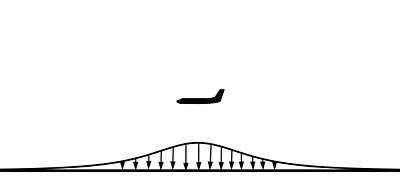
When a ground plane is present, there is a pattern of higher-than-ambient pressure on the ground below an airplane in flight, as shown on the right[92] For steady, level flight, the integrated pressure force associated with this pattern is equal to the total aerodynamic lift of the airplane and to the airplane's weight. According to Newton's third law, this pressure force exerted on the ground by the air is matched by an equal-and-opposite upward force exerted on the air by the ground, which offsets all of the downward force exerted on the air by the airplane. The net force due to the lift, acting on the atmosphere as a whole, is therefore zero, and there is thus no integrated accumulation of vertical momentum in the atmosphere.[93]
Lift of three-dimensional wings
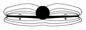
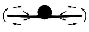
For wings of moderate-to-high aspect ratio, the flow at any station along the span except close to the tips behaves much like flow around a two-dimensional airfoil, and most explanations of lift, like those above, concentrate on two-dimensional flow. However, even for wings of high aspect ratio, the three-dimensional effects associated with finite span are significant across the whole span, not just close to the tips.
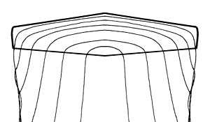
The lift tends to decrease in the spanwise direction from root to tip, and the pressure distributions around the airfoil sections change accordingly in the spanwise direction. Pressure distributions in planes perpendicular to the flight direction tend to look like the illustration at right.[94] This spanwise-varying pressure distribution is sustained by a mutual interaction with the velocity field. Flow below the wing is accelerated outboard, flow outboard of the tips is accelerated upward, and flow above the wing is accelerated inboard, which results in the flow pattern illustrated at right.[95]
There is more downward turning of the flow than there would be in a two-dimensional flow with the same airfoil shape and sectional lift, and a higher sectional angle of attack is required to achieve the same lift compared to a two-dimensional flow.[96] The wing is effectively flying in a downdraft of its own making, as if the freestream flow were tilted downward, with the result that the total aerodynamic force vector is tilted backward slightly compared to what it would be in two dimensions. The additional backward component of the force vector is called lift-induced drag.
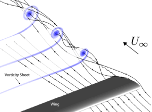
The difference in the spanwise component of velocity above and below the wing (between being in the inboard direction above and in the outboard direction below) persists at the trailing edge and into the wake downstream. After the flow leaves the trailing edge, this difference in velocity takes place across a relatively thin shear layer called a vortex sheet. As the vortex sheet is convected downstream from the trailing edge, it rolls up at its outer edges, eventually forming distinct wingtip vortices. The combination of the wingtip vortices and the vortex sheets feeding them is called the vortex wake.
In addition to the vorticity in the trailing vortex wake there is vorticity in the wing's boundary layer, which is often called the bound vorticity and which connects the trailing sheets from the two sides of the wing into a vortex system in the general form of a horseshoe. The horseshoe form of the vortex system was recognized by the British aeronautical pioneer Lanchester in 1907.[97]
Given the distribution of bound vorticity and the vorticity in the wake, the Biot-Savart law (a vector-calculus relation) can be used to calculate the velocity perturbation anywhere in the field, caused by the lift on the wing. Approximate theories for the lift distribution and lift-induced drag of three-dimensional wings are based on such analysis applied to the wing's horseshoe vortex system.[98][99] In these theories, the bound vorticity is usually idealized and assumed to reside at the camber surface inside the wing.
Because the velocity is deduced from the vorticity in such theories, there is a tendency for some authors to describe the situation in terms that imply that the vorticity is the cause of the velocity perturbations, using terms such as "the velocity induced by the vortex," for example.[100] But attributing causation to the vorticity in this way is not consistent with the physics. The real cause of the velocity perturbations is the pressure field.[101][102][103]
Viscous effects: Profile drag and stalling

No matter how smooth the surface of an airfoil seems, any real surface is rough on the scale of air molecules. Air molecules flying into the surface bounce off the rough surface in random directions not related to their incoming directions. The result is that when the air is viewed as if it were a continuous material, it is seen to be unable to slide along the surface, and the air's tangential velocity at the surface goes to practically zero, something known as the no-slip condition.[104] Because the air at the surface has near-zero velocity, and air away from the surface is moving, there is a thin boundary layer in which the air close to the surface is subjected to a shearing motion.[105][106] The air's viscosity resists the shearing, giving rise to a shear stress at the airfoil's surface called skin-friction drag. Over most of the surface of most airfoils, the boundary layer is naturally turbulent, which increases skin-friction drag.[106][107]
Under usual flight conditions, the boundary layer remains attached to both the upper and lower surfaces all the way to the trailing edge, and its effect on the rest of the flow is modest. Compared to the predictions of inviscid-flow theory, in which there is no boundary layer, the attached boundary layer reduces the lift by a modest amount and modifies the pressure distribution somewhat, which results in a viscosity-related pressure drag over and above the skin-friction drag. The total of the skin-friction drag and the viscosity-related pressure drag is usually called the profile drag.[107][108]
The maximum lift an airfoil can produce at a given airspeed is limited by boundary-layer separation. As the angle of attack is increased, a point is reached where the boundary layer can no longer remain attached to the upper surface. When the boundary layer separates, it leaves a region of recirculating flow above the upper surface, as illustrated in the flow-visualization photo at right. This is known as the stall, or stalling. At angles of attack above the stall, lift is significantly reduced, though it is not zero. The maximum lift that can be achieved before stall, in terms of the lift coefficient, is generally less than 2.0 for single-element airfoils and can be more than 3.0 for airfoils with high-lift slotted flaps deployed.[109]
Lift forces on bluff bodies
The flow around bluff bodies – i.e. without a streamlined shape, or stalling airfoils – may also generate lift, besides a strong drag force. This lift may be steady, or it may oscillate due to vortex shedding. Interaction of the object's flexibility with the vortex shedding may enhance the effects of fluctuating lift and cause vortex-induced vibrations.[110] For instance, the flow around a circular cylinder generates a Kármán vortex street: vortices being shed in an alternating fashion from each side of the cylinder. The oscillatory nature of the flow is reflected in the fluctuating lift force on the cylinder, whereas the mean lift force is negligible. The lift force frequency is characterised by the dimensionless Strouhal number, which depends (among others) on the Reynolds number of the flow.[111][112]
For a flexible structure, this oscillatory lift force may induce vortex-induced vibrations. Under certain conditions – for instance resonance or strong spanwise correlation of the lift force – the resulting motion of the structure due to the lift fluctuations may be strongly enhanced. Such vibrations may pose problems and threaten collapse in tall man-made structures like industrial chimneys.[110]
In the Magnus effect, a lift force is generated by a spinning cylinder in a freestream. Here the mechanical rotation acts on the boundary layer, causing it to separate at different locations on the two sides of the cylinder. The asymmetric separation changes the effective shape of the cylinder as far as the flow is concerned such that the cylinder acts like a lifting airfoil with circulation in the outer flow.[113]
Alternative explanations, misconceptions, and controversies
Many other alternative explanations for the generation of lift by an airfoil have been put forward, a few of which are presented here. Most of them are intended to explain the phenomenon of lift to a general audience. Although the explanations may share features in common with the explanations above, additional assumptions and simplifications may be introduced. This can reduce the validity of an alternative explanation to a limited sub-class of lift generating conditions, or might not allow a quantitative analysis. Several theories introduce assumptions which proved to be wrong, like the equal transit-time theory.
False explanation based on equal transit-time
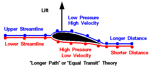
Basic or popular sources often describe the "equal transit-time" theory of lift, which incorrectly assumes that the parcels of air that divide at the leading edge of an airfoil must rejoin at the trailing edge, forcing the air traveling along the longer upper surface to go faster. Bernoulli's Principle is then cited to conclude that since the air moves slower along the bottom of the wing, the air pressure must be higher, pushing the wing up.[114]
However, there is no physical principle that requires equal transit time and experimental results show that this assumption is false.[115][116][117][118][119][120] In fact, the air moving over the top of an airfoil generating lift moves much faster than the equal transit theory predicts.[121] Further, the theory violates Newton's third law of motion, since it describes a force on the wing with no opposite force.[122]
The assertion that the air must arrive simultaneously at the trailing edge is sometimes referred to as the "Equal Transit-Time Fallacy".[123][124][125][126][127]
Controversy regarding the Coandă effect
In its original sense, the Coandă effect refers to the tendency of a fluid jet to stay attached to an adjacent surface that curves away from the flow, and the resultant entrainment of ambient air into the flow. The effect is named for Henri Coandă, the Romanian aerodynamicist who exploited it in many of his patents.
More broadly, some consider the effect to include the tendency of any fluid boundary layer to adhere to a curved surface, not just the boundary layer accompanying a fluid jet. It is in this broader sense that the Coandă effect is used by some to explain why the air flow remains attached to the top side of an airfoil.[128] Jef Raskin,[129] for example, describes a simple demonstration, using a straw to blow over the upper surface of a wing. The wing deflects upwards, thus demonstrating that the Coandă effect creates lift. This demonstration correctly demonstrates the Coandă effect as a fluid jet (the exhaust from a straw) adhering to a curved surface (the wing). However, the upper surface in this flow is a complicated, vortex-laden mixing layer, while on the lower surface the flow is quiescent. The physics of this demonstration are very different from that of the general flow over the wing.[130] The usage in this sense is encountered in some popular references on aerodynamics.[128][129] This is a controversial use of the term "Coanda effect." The more established view in the aerodynamics field is that the Coandă effect is defined in the more limited sense above,[130][131][132] and the flow following the upper surface simply reflects an absence of boundary-layer separation and is not an example of the Coandă effect.[133][134][135][136]
Misconception regarding the role of viscosity
Explanations that use the term "Coandă effect" sometimes further assert that the viscosity of the flow in the boundary layer is responsible for the ability of the flow to follow the convex upper surface.[137][138] However, the idea that viscosity plays a significant role in flow turning is not consistent with the physics of curved boundary-layer flows. Analysis of the momentum balance in the flow in the boundary layer shows that the flow curvature is caused almost exclusively by the pressure gradient and that viscosity plays practically no direct role in the ability of the flow to follow a curved surface.[139]
Misconception regarding "pulling down" of the flow
Explanations that refer to the Coandă effect sometimes also refer to the flow over the upper surface as "sticking" to the airfoil and being "pulled down" to follow the surface.[137] Taken literally, this description is not consistent with the physics of gasses. For air to be pulled in the literal sense, it would have to be put in tension (negative pressure). The kinetic theory of gasses shows that in a gas at a positive absolute temperature the pressure cannot be negative.[55] Thus for the flow to curve downward over the upper surface, it must be pushed down by higher pressure above than below.[140] The difference in pressure between the flow at the upper surface itself and the flow far above the airfoil is generally small compared with the background atmospheric pressure, so that the lowest pressure on the airfoil upper surface is still strongly positive in an absolute sense.[141]
See also
- Bilgeboard
- Boomerang
- Centerboard
- Circulation control wing
- Diving plane
- Downforce
- Drag coefficient
- Drag (physics)
- Fin
- Flipper (anatomy)
- Flow separation
- Fluid
- Fluid dynamics
- Foil (fluid mechanics)
- Formula One car
- Glider
- Hydrofoil
- Keel (hydrodynamic)
- Küssner effect
- Lift coefficient
- Lift-induced drag
- Lift-to-drag ratio
- Lifting-line theory
- Newton's third law
- Propeller
- Sail (aerodynamics)
- Skeg
- Spoiler (automotive)
- Stall (fluid mechanics)
- Surfboard fin
- Wingtip vortices
Footnotes
- ↑ "What is Lift?". NASA Glenn Research Center. Retrieved March 4, 2009.
- ↑ Kulfan (2010)
- ↑ The amount of lift will be (usually slightly) more or less than gravity depending on the thrust level and vertical alignment of the thrust line. A side thrust line will result in some lift opposing side thrust as well.
- ↑ Clancy, L. J., Aerodynamics, Section 14.6
- ↑ Clancy, L. J., Aerodynamics, Section 5.2
- 1 2 "There are many theories of how lift is generated. Unfortunately, many of the theories found in encyclopedias, on web sites, and even in some textbooks are incorrect, causing unnecessary confusion for students." NASA http://www.grc.nasa.gov/WWW/K-12/airplane/wrong1.html
- ↑ "Most of the texts present the Bernoulli formula without derivation, but also with very little explanation. When applied to the lift of an airfoil, the explanation and diagrams are almost always wrong. At least for an introductory course, lift on an airfoil should be explained simply in terms of Newton’s Third Law, with the thrust up being equal to the time rate of change of momentum of the air downwards." Cliff Swartz et al. Quibbles, Misunderstandings, and Egregious Mistakes - Survey of High-School Physics Texts THE PHYSICS TEACHER Vol. 37, May 1999 pg 300 http://scitation.aip.org/getpdf/servlet/GetPDFServlet?filetype=pdf&id=PHTEAH000037000005000297000001&idtype=cvips&doi=10.1119/1.880292&prog=normal
- 1 2 "One explanation of how a wing of an airplane gives lift is that as a result of the shape of the airfoil, the air flows faster over the top than it does over the bottom because it has farther to travel. Of course, with our thin-airfoil sails, the distance along the top is the same as along the bottom so this explanation of lift fails." The Aerodynamics of Sail Interaction by Arvel Gentry Proceedings of the Third AIAA Symposium on the Aero/Hydronautics of Sailing 1971 http://www.arvelgentry.com/techs/The%20Aerodynamics%20of%20Sail%20Interaction.pdf
- 1 2 "An explanation frequently given is that the path along the upper side of the aerofoil is longer and the air thus has to be faster. This explanation is wrong." A comparison of explanations of the aerodynamic lifting force Klaus Weltner Am. J. Phys. Vol.55 No.January 1, 1987
- 1 2 "The lift on the body is simple...it's the re-action of the solid body to the turning of a moving fluid...Now why does the fluid turn the way that it does? That's where the complexity enters in because we are dealing with a fluid. ...The cause for the flow turning is the simultaneous conservation of mass, momentum (both linear and angular), and energy by the fluid. And it's confusing for a fluid because the mass can move and redistribute itself (unlike a solid), but can only do so in ways that conserve momentum (mass times velocity) and energy (mass times velocity squared)... A change in velocity in one direction can cause a change in velocity in a perpendicular direction in a fluid, which doesn't occur in solid mechanics... So exactly describing how the flow turns is a complex problem; too complex for most people to visualize. So we make up simplified "models". And when we simplify, we leave something out. So the model is flawed. Most of the arguments about lift generation come down to people finding the flaws in the various models, and so the arguments are usually very legitimate." Tom Benson of NASA's Glenn Research Center in an interview with AlphaTrainer.Com http://www.alphatrainer.com/pages/corner.htm
- ↑ "Both approaches are equally valid and equally correct, a concept that is central to the conclusion of this article." Charles N. Eastlake An Aerodynamicist’s View of Lift, Bernoulli, and Newton THE PHYSICS TEACHER Vol. 40, March 2002 http://www.df.uba.ar/users/sgil/physics_paper_doc/papers_phys/fluids/Bernoulli_Newton_lift.pdf
- ↑ Ison, David, "Bernoulli Or Newton: Who's Right About Lift?", Plane & Pilot, retrieved January 14, 2011
- ↑ "...the effect of the wing is to give the air stream a downward velocity component. The reaction force of the deflected air mass must then act on the wing to give it an equal and opposite upward component." In: Halliday, David; Resnick, Robert, Fundamentals of Physics 3rd Edition, John Wiley & Sons, p. 378
- 1 2 Anderson and Eberhardt (2001)
- 1 2 Langewiesche (1944)
- ↑ "When air flows over and under an airfoil inclined at a small angle to its direction, the air is turned from its course. Now, when a body is moving in a uniform speed in a straight line, it requires force to alter either its direction or speed. Therefore, the sails exert a force on the wind and, since action and reaction are equal and opposite, the wind exerts a force on the sails." In: Morwood, John, Sailing Aerodynamics, Adlard Coles Limited, p. 17
- ↑ "Lift is a force generated by turning a moving fluid... If the body is shaped, moved, or inclined in such a way as to produce a net deflection or turning of the flow, the local velocity is changed in magnitude, direction, or both. Changing the velocity creates a net force on the body." "Lift from Flow Turning". NASA Glenn Research Center. Retrieved July 7, 2009.
- 1 2 Landau, L. D.; Lifshitz, E. M. (1987), Fluid mechanics, Course of Theoretical Physics, 6 (2nd revised ed.), Pergamon Press, pp. 68–69, 153–155, ISBN 0-08-033932-8, OCLC 15017127
- ↑ "Essentially, due to the presence of the wing (its shape and inclination to the incoming flow, the so-called angle of attack), the flow is given a downward deflection, as shown in Fig. 2. It is Newton’s third law at work here, with the flow then exerting a reaction force on the wing in an upward direction, thus generating lift." Vassilis Spathopoulos Flight Physics for Beginners: Simple Examples of Applying Newton’s Laws The Physics Teacher Vol. 49, September 2011 pg 373 http://tpt.aapt.org/resource/1/phteah/v49/i6/p373_s1
- ↑ "The main fact of all heavier-than-air flight is this: the wing keeps the airplane up by pushing the air down." In: Langewiesche, Wolfgang (1990), Stick and Rudder: An Explanation of the Art of Flying, McGraw-Hill, pp. 6–10, ISBN 0-07-036240-8
- ↑ "Birds and aircraft fly because they are constantly pushing air downwards: L = dp/dt Here L is the lift force and dp/dt is the rate at which downward momentum is imparted to the airflow." Flight without Bernoulli Chris Waltham THE PHYSICS TEACHER Vol. 36, Nov. 1998 http://www.df.uba.ar/users/sgil/physics_paper_doc/papers_phys/fluids/fly_no_bernoulli.pdf
- ↑ Clancy, L. J.; Aerodynamics, Pitman 1975, page 76: "This lift force has its reaction in the downward momentum which is imparted to the air as it flows over the wing. Thus the lift of the wing is equal to the rate of transport of downward momentum of this air."
- ↑ "...if the air is to produce an upward force on the wing, the wing must produce a downward force on the air. Because under these circumstances air cannot sustain a force, it is deflected, or accelerated, downward. Newton's second law gives us the means for quantifying the lift force: Flift = m∆v/∆t = ∆(mv)/∆t. The lift force is equal to the time rate of change of momentum of the air." Norman F. Smith "Bernoulli and Newton in Fluid Mechanics" The Physics Teacher 10, 451 (1972); doi:10.1119/1.2352317
- ↑ "L = time rate of change of momentum of airflow in the downward direction"[25]
- 1 2 3 Anderson (2004).
- ↑ Doug McLean Understanding Aerodynamics: Arguing from the Real Physics Section 7.3.3 Wiley http://onlinelibrary.wiley.com/doi/10.1002/9781118454190.ch3/pdf
- ↑ "A complete statement of Bernoulli's Theorem is as follows: "In a flow where no energy is being added or taken away, the sum of its various energies is a constant: consequently where the velocity increases the pressure decreases and vice versa." Smith, Norman F. "Bernoulli, Newton and Dynamic Lift Part I". School Science and Mathematics. 73 (3): 181–186. doi:10.1111/j.1949-8594.1973.tb08998.x.
- ↑ "The effect of squeezing streamlines together as they divert around the front of an airfoil shape is that the velocity must increase to keep the mass flow constant since the area between the streamlines has become smaller." Charles N. Eastlake An Aerodynamicist’s View of Lift, Bernoulli, and Newton THE PHYSICS TEACHER Vol. 40, March 2002 http://www.df.uba.ar/users/sgil/physics_paper_doc/papers_phys/fluids/Bernoulli_Newton_lift.pdf
- ↑ "There is no way to predict, from Bernoulli's equation alone, what the pattern of streamlines will be for a particular wing." Halliday and Resnick Fundamentals of Physics 3rd Ed. Extended pg 378
- ↑ "The generation of lift may be explained by starting from the shape of streamtubes above and below an airfoil. With a constriction above and an expansion below, it is easy to demonstrate lift, again via the Bernoulli equation. However, the reason for the shape of the streamtubes remains obscure..." Jaakko Hoffren Quest for an Improved Explanation of Lift American Institute of Aeronautics and Astronautics 2001 pg 3 http://corsair.flugmodellbau.de/files/area2/LIFT.PDF
- ↑ "There is nothing wrong with the Bernoulli principle, or with the statement that the air goes faster over the top of the wing. But, as the above discussion suggests, our understanding is not complete with this explanation. The problem is that we are missing a vital piece when we apply Bernoulli’s principle. We can calculate the pressures around the wing if we know the speed of the air over and under the wing, but how do we determine the speed?" How Airplanes Fly: A Physical Description of Lift David Anderson and Scott Eberhardt http://www.allstar.fiu.edu/aero/airflylvl3.htm
- ↑ "The problem with the "Venturi" theory is that it attempts to provide us with the velocity based on an incorrect assumption (the constriction of the flow produces the velocity field). We can calculate a velocity based on this assumption, and use Bernoulli's equation to compute the pressure, and perform the pressure-area calculation and the answer we get does not agree with the lift that we measure for a given airfoil." NASA Glenn Research Center http://www.grc.nasa.gov/WWW/K-12/airplane/wrong3.html
- ↑ "A concept...uses a symmetrical convergent-divergent channel, like a longitudinal section of a Venturi tube, as the starting point. It is widely known that, when such a device is put in a flow, the static pressure in the tube decreases. When the upper half of the tube is removed, a geometry resembling the airfoil is left, and suction is still maintained on top of it. Of course, this explanation is flawed too, because the geometry change affects the whole flowfield and there is no physics involved in the description." Jaakko Hoffren Quest for an Improved Explanation of Lift Section 4.3 American Institute of Aeronautics and Astronautics 2001 http://corsair.flugmodellbau.de/files/area2/LIFT.PDF
- ↑ "This answers the apparent mystery of how a symmetric airfoil can produce lift. ... This is also true of a flat plate at non-zero angle of attack." Charles N. Eastlake An Aerodynamicist’s View of Lift, Bernoulli, and Newton http://www.df.uba.ar/users/sgil/physics_paper_doc/papers_phys/fluids/Bernoulli_Newton_lift.pdf
- ↑ "This classic explanation is based on the difference of streaming velocities caused by the airfoil. There remains, however, a question: How does the airfoil cause the difference in streaming velocities? Some books don't give any answer, while others just stress the picture of the streamlines, saying the airfoil reduces the separations of the streamlines at the upper side (Fig. 1). They do not say how the airfoil manages to do this. Thus this is not a sufficient answer." Klaus Weltner Bernoulli's Law and Aerodynamic Lifting Force The Physics Teacher February 1990 p. 84. http://scitation.aip.org/getpdf/servlet/GetPDFServlet?filetype=pdf&id=PHTEAH000028000002000084000001&idtype=cvips&prog=normal
- ↑ "...there is nothing in aerodynamics requiring the top and bottom flows having to reach the trailing edge at the same time. This idea is a completely erroneous explanation for lift. The flow on top gets to the trailing edge long before the flow on the bottom because of the circulation flow field." Arvel Gentry Origins of Lift http://www.arvelgentry.com/techs/origins_of_lift.pdf
- ↑ A uniform pressure surrounding a body does not create a net force. (See buoyancy). Therefore pressure differences are needed to exert a force on a body immersed in a fluid. For example, see: Batchelor, G.K. (1967), An Introduction to Fluid Dynamics, Cambridge University Press, pp. 14–15, ISBN 0-521-66396-2
- ↑ "...if a streamline is curved, there must be a pressure gradient across the streamline..."Babinsky, Holger (November 2003), "How do wings work?" (PDF), Physics Education
- ↑ Thus a distribution of the pressure is created which is given in Euler's equation. The physical reason is the aerofoil which forces the streamline to follow its curved surface. The low pressure at the upper side of the aerofoil is a consequence of the curved surface." A comparison of explanations of the aerodynamic lifting force Klaus Weltner Am. J. Phys. Vol.55 No.January 1, 1987 pg 53 http://scitation.aip.org/getpdf/servlet/GetPDFServlet?filetype=pdf&id=AJPIAS000055000001000050000001&idtype=cvips&doi=10.1119/1.14960&prog=normal
- ↑ "You can argue that the main lift comes from the fact that the wing is angled slightly upward so that air striking the underside of the wing is forced downward. The Newton's 3rd law reaction force upward on the wing provides the lift. Increasing the angle of attack can increase the lift, but it also increases drag so that you have to provide more thrust with the aircraft engines" hyperphysics Georgia State University Department of Physics and Astronomy http://hyperphysics.phy-astr.gsu.edu/hbase/fluids/angatt.html
- ↑ "If we enlarge the angle of attack we enlarge the deflection of the airstream by the airfoil. This results in the enlargement of the vertical component of the velocity of the airstream... we may expect that the lifting force depends linearly on the angle of attack. This dependency is in complete agreement with the results of experiments..." Klaus Weltner A comparison of explanations of the aerodynamic lifting force Am. J. Phys. 55(1), January 1987 pg 52
- ↑ "The decrease of angles exceeding 25° is plausible. For large angles of attack we get turbulence and thus less deflection downward." Klaus Weltner A comparison of explanations of the aerodynamic lifting force Am. J. Phys. 55(1), January 1987 pg 52
- ↑ Clancy (1975), Section 5.2
- ↑ Abbott, and von Doenhoff (1958), Section 4.2
- ↑ "With an angle of attack of 0°, we can explain why we already have a lifting force. The air stream behind the aerofoil follows the trailing edge. The trailing edge already has a downward direction, if the chord to the middle line of the profile is horizontal." Klaus Weltner A comparison of explanations of the aerodynamic lifting force Am. J. Phys. 55(1), January 1987 p. 52
- ↑ "...the important thing about an aerofoil (say an aircraft wing) is not so much that its upper surface is humped and its lower surface is nearly flat, but simply that it moves through the air at an angle. This also avoids the otherwise difficult paradox that an aircraft can fly upside down!" N. H. Fletcher Mechanics of Flight Physics Education July 1975 http://iopscience.iop.org/0031-9120/10/5/009/pdf/0031-9120_10_5_009.pdf
- ↑ "It requires adjustment of the angle of attack, but as clearly demonstrated in almost every air show, it can be done." hyperphysics Georgia State University Department of Physics and Astronomy http://hyperphysics.phy-astr.gsu.edu/hbase/fluids/airfoil.html#c2
- ↑ Abbott and von Doenhoff (1958), Section 1.2
- ↑ Milne-Thomson (1966), Section 12.3
- ↑ Anderson, John D. (2004), Introduction to Flight (5th ed.), McGraw-Hill, pp. 257–261, ISBN 0-07-282569-3
- ↑ Yoon, Joe (2003-12-28), Mach Number & Similarity Parameters, Aerospaceweb.org, retrieved 2009-02-11
- ↑ Anderson (2008), Section 5.7
- 1 2 3 4 McLean (2012), Section 7.3.3
- 1 2 Milne-Thomson (1966), Section 1.41
- 1 2 Jeans (1967), Section 33.
- 1 2 3 Clancy (1975), Section 4.5
- ↑ Milne-Thomson (1966.), Section 5.31
- ↑ McLean (2012), Section 3.5
- ↑ Batchelor (1967), Section 1.2
- ↑ Thwaites (1958), Section I.2
- ↑ von Mises (1959), Section I.1
- ↑ Durand (1932), Section D, Historical Sketch by R. Giacomelli
- ↑ Anderson (1997)
- ↑ McLean (2012), Sections 7.3.1.1 and 7.3.2
- ↑ Weltner (1987), pg 53
- ↑ "What is Lift?". NASA Glenn Research Center. Retrieved March 4, 2009.
- ↑ "Analysis of fluid flow is typically presented to engineering students in terms of three fundamental principles: conservation of mass, conservation of momentum, and conservation of energy." Charles N. Eastlake An Aerodynamicist’s View of Lift, Bernoulli, and Newton THE PHYSICS TEACHER Vol. 40, March 2002 http://www.df.uba.ar/users/sgil/physics_paper_doc/papers_phys/fluids/Bernoulli_Newton_lift.pdf
- ↑ White(1991), Chapter 1
- ↑ Batchelor (1967), Chapter 3
- ↑ Aris (1989)
- 1 2 Spalart(2000) Amsterdam, The Netherlands. Elsevier Science Publishers.
- ↑ White(1991), Section 6-2
- ↑ Schlichting(1979), Chapter XVIII
- ↑ Anderson (1995)
- ↑ "...whenever the velocity field is irrotational, it can be expressed as the gradient of a scalar function we call a velocity potential φ: V = ∇φ. The existence of a velocity potential can greatly simplify the analysis of inviscid flows by way of potential-flow theory..." Doug McLean Understanding Aerodynamics: Arguing from the Real Physics p 26 Wiley http://onlinelibrary.wiley.com/doi/10.1002/9781118454190.ch3/pdf
- ↑ Elements of Potential Flow California State University Los Angeles http://instructional1.calstatela.edu/cwu/me408/Slides/PotentialFlow/PotentialFlow.htm
- ↑ Batchelor(1967), Section 2.7
- ↑ Milne-Thomson(1966), Section 3.31
- ↑ Clancy (1975), Section 4.8
- ↑ Anderson(1991), Section 4.5
- ↑ Clancy(1975), Sections 8.1-8
- 1 2 von Mises (1959), Section VIII.2
- 1 2 Anderson(1991), Section 3.15
- ↑ Prandtl and Tietjens (1934)
- ↑ Batchelor (1967), Section 6.7
- ↑ Gentry (2006)
- ↑ McLean (2012), Section 7.2.1
- ↑ Shapiro (1953), Section 1.5
- 1 2 3 4 Lissaman (1996), Section titled "Lift in thin slices: the two dimensional case"
- 1 2 3 Durand (1932), Sections B. V. 6 and B. V. 7
- 1 2 3 Batchelor (1967), Section 6.4, p. 407
- ↑ Prandtl and Tietjens (1934), Figure 150
- ↑ Lanchester (1907), Sections 1-6
- ↑ McLean (2012), Section 8.1.3
- ↑ McLean (2012), Section 8.1.1
- ↑ Hurt, H. H. (1965) Aerodynamics for Naval Aviators, Figure 1.30, NAVWEPS 00-80T-80
- ↑ Lanchester (1907)
- ↑ Milne-Thomson (1966), Section 10.1
- ↑ Clancy (1975), Section 8.9
- ↑ Anderson (1991), Section 5.2
- ↑ Batchelor (1967), Section 2.4
- ↑ Milne-Thomson (1966), Section 9.3
- ↑ Durand (1932), Section III.2
- ↑ White (1991), Section 1-4
- ↑ White (1991), Section 1-2
- 1 2 Anderson (1991), Chapter 17
- 1 2 Abbott and von Doenhoff (1958), Chapter 5
- ↑ Schlichting (1979), Chapter XXIV
- ↑ Abbott and Doenhoff (1958), Chapter 8
- 1 2 Williamson, C.H.K.; Govardhan, R. (2004), "Vortex-induced vibrations", Annual Review of Fluid Mechanics, 36: 413–455, Bibcode:2004AnRFM..36..413W, doi:10.1146/annurev.fluid.36.050802.122128
- ↑ Sumer, B. Mutlu; Fredsøe, Jørgen (2006), Hydrodynamics around cylindrical structures (revised ed.), World Scientific, pp. 6–13, 42–45 & 50–52, ISBN 981-270-039-0
- ↑ Zdravkovich, M.M. (2003), Flow around circular cylinders, 2, Oxford University Press, pp. 850–855, ISBN 0-19-856561-5
- ↑ Clancy, L. J., Aerodynamics, Sections 4.5 and 4.6
- ↑ "The airfoil of the airplane wing, according to the textbook explanation that is more or less standard in the United States, has a special shape with more curvature on top than on the bottom; consequently, the air must travel farther over the top surface than over the bottom surface. Because the air must make the trip over the top and bottom surfaces in the same elapsed time ..., the velocity over the top surface will be greater than over the bottom. According to Bernoulli's theorem, this velocity difference produces a pressure difference which is lift." Bernoulli and Newton in Fluid Mechanics Norman F. Smith The Physics Teacher November 1972 Volume 10, Issue 8, pp. 451 http://scitation.aip.org/getpdf/servlet/GetPDFServlet?filetype=pdf&id=PHTEAH000010000008000451000001&idtype=cvips&doi=10.1119/1.2352317&prog=normal
- ↑ "Unfortunately, this explanation falls to earth on three counts. First, an airfoil need not have more curvature on its top than on its bottom. Airplanes can and do fly with perfectly symmetrical airfoils; that is with airfoils that have the same curvature top and bottom. Second, even if a humped-up (cambered) shape is used, the claim that the air must traverse the curved top surface in the same time as it does the flat bottom surface...is fictional. We can quote no physical law that tells us this. Third—and this is the most serious—the common textbook explanation, and the diagrams that accompany it, describe a force on the wing with no net disturbance to the airstream. This constitutes a violation of Newton's third law." Bernoulli and Newton in Fluid Mechanics Norman F. Smith The Physics Teacher November 1972 Volume 10, Issue 8, pp. 451 http://tpt.aapt.org/resource/1/phteah/v10/i8
- ↑ Anderson, David (2001), Understanding Flight, New York: McGraw-Hill, pp. 15–16, ISBN 0-07-136377-7,
The first thing that is wrong is that the principle of equal transit times is not true for a wing with lift.
- ↑ Anderson, John (2005). Introduction to Flight. Boston: McGraw-Hill Higher Education. p. 355. ISBN 0072825693.
It is then assumed that these two elements must meet up at the trailing edge, and because the running distance over the top surface of the airfoil is longer than that over the bottom surface, the element over the top surface must move faster. This is simply not true
- ↑ http://www.telegraph.co.uk/science/science-news/9035708/Cambridge-scientist-debunks-flying-myth.html Cambridge scientist debunks flying myth UK Telegraph 24 Jan 2012
- ↑ Flow Visualization. National Committee for Fluid Mechanics Films/Educational Development Center. Retrieved January 21, 2009. A visualization of the typical retarded flow over the lower surface of the wing and the accelerated flow over the upper surface starts at 5:29 in the video.
- ↑ "...do you remember hearing that troubling business about the particles moving over the curved top surface having to go faster than the particles that went underneath, because they have a longer path to travel but must still get there at the same time? This is simply not true. It does not happen." Charles N. Eastlake An Aerodynamicist’s View of Lift, Bernoulli, and Newton THE PHYSICS TEACHER Vol. 40, March 2002 PDF
- ↑ "The actual velocity over the top of an airfoil is much faster than that predicted by the "Longer Path" theory and particles moving over the top arrive at the trailing edge before particles moving under the airfoil."Glenn Research Center (March 15, 2006). "Incorrect Lift Theory". NASA. Retrieved August 12, 2010.
- ↑ "...the air is described as producing a force on the object without the object having any opposite effect on the air. Such a condition, we should quickly recognize, embodies an action without a reaction, which is, according to Newton’s Third Law, impossible." Norman F. Smith Bernoulli, Newton,and Dynamic Lift Part I School Science and Mathematics, 73, 3, Mar 1973 http://eric.ed.gov/?id=EJ075197
- ↑ A false explanation for lift has been put forward in mainstream books, and even in scientific exhibitions. Known as the "equal transit-time" explanation, it states that the parcels of air which are divided by an airfoil must rejoin again; because of the greater curvature (and hence longer path) of the upper surface of an aerofoil, the air going over the top must go faster in order to "catch up" with the air flowing around the bottom. Therefore, because of its higher speed the pressure of the air above the airfoil must be lower. Despite the fact that this "explanation" is probably the most common of all, it is false. It has recently been dubbed the "Equal transit-time fallacy"."Fixed wing aircraft facts and how aircraft fly". Retrieved July 7, 2009.
- ↑ ...it leaves the impression that Professor Bernoulli is somehow to blame for the "equal transit time" fallacy... John S. Denker (1999). "Critique of "How Airplanes Fly"". Retrieved July 7, 2009.
- ↑ The fallacy of equal transit time can be deduced from consideration of a flat plate, which will indeed produce lift, as anyone who has handled a sheet of plywood in the wind can testify. Gale M. Craig. "Physical principles of winged flight". Retrieved July 7, 2009.
- ↑ Fallacy 1: Air takes the same time to move across the top of an aerofoil as across the bottom. Peter Eastwell (2007), "Bernoulli? Perhaps, but What About Viscosity?" (PDF), The Science Education Review, 6 (1), retrieved July 14, 2009.
- ↑ "There is a popular fallacy called the equal transit-time fallacy that claims the two halves rejoin at the trailing edge of the aerofoil." Ethirajan Rathakrishnan Theoretical Aerodynamics John Wiley & sons 2013 section 4.10.1
- 1 2 Anderson, David; Eberhart, Scott (1999), How Airplanes Fly: A Physical Description of Lift, retrieved June 4, 2008
- 1 2 Raskin, Jef (1994), Coanda Effect: Understanding Why Wings Work, archived from the original on September 28, 2007
- 1 2 Auerbach, David (2000), "Why Aircraft Fly", Eur. J. Phys., 21 (4): 289–296, Bibcode:2000EJPh...21..289A, doi:10.1088/0143-0807/21/4/302
- ↑ Denker, JS, Fallacious Model of Lift Production, retrieved 2008-08-18
- ↑ Wille, R.; Fernholz, H. (1965), "Report on the first European Mechanics Colloquium, on the Coanda effect", J. Fluid Mech., 23 (4): 801–819, Bibcode:1965JFM....23..801W, doi:10.1017/S0022112065001702
- ↑ Auerbach (2000)
- ↑ Denker (1996)
- ↑ Wille and Fernholz(1965)
- ↑ White, Frank M. (2002), Fluid Mechanics (5th ed.), McGraw Hill
- 1 2 Raskin (1994)
- ↑ Anderson, D. F., Eberhardt, S. , 2001, states that "differences in speed in adjacent layers cause shear forces, which cause the flow of the fluid to want to bend in the direction of the slower layer." This assertion is not consistent with the actual momentum balance in a curved boundary-layer flow. See equation 4c in Van Dyke (1969), for example.
- ↑ Van Dyke (1969). The derivation of equation 4c shows that the contribution of viscous stress to flow turning is negligible.
- ↑ Babinsky (2003)
- ↑ McLean (2012), Sections 7.3.3.9 and 7.3.3.13
References
- Abbott, I. H.; von Doenhoff, A. E. (1958), Theory of Wing Sections, Dover Publications
- Anderson, D. F.; Eberhardt, S. (2001), Understanding Flight, McGraw-Hill.
- Anderson, J. D. (1991), , Fundamentals of Aerodynamics, 2nd edition, McGraw-Hill
- Anderson, J. D. (1995), Computational Fluid Dynamics, The Basics With Applications, ISBN 0-07-113210-4
- Anderson, J. D. (1997), A History of Aerodynamics, Cambridge University Press.
- Anderson, John D. (2004), Introduction to Flight (5th ed.), McGraw-Hill, pp. 352–361, §5.19, ISBN 0-07-282569-3
- Anderson, J. D. (2008), Introduction to Flight, 6th edition, McGraw Hill.
- Aris, R. (1989), Vectors, Tensors, and the basic Equations of Fluid Mechanics, Dover Publications
- Auerbach, D. (2000), Why Aircraft Fly, Eur. J. Phys. 21 (4): 289–296
- Babinsky, H. (2003), How do wings work?, Phys. Educ., vol. 38, p. 497.
- Batchelor, G. K. (1967), An Introduction to Fluid Dynamics, Cambridge University Press
- Clancy, L. J. (1975), Aerodynamics, Longman Scientific and Technical
- Craig, G. M. (1997), Stop Abusing Bernoulli, Anderson, Indiana: Regenerative Press
- Durand, W. F., ed. (1932), Aerodynamic Theory, vol. 1, Dover Publications
- Eastlake, C. N. (2002), An Aerodynamicist’s View of Lift, Bernoulli, and Newton, THE PHYSICS TEACHER Vol. 40
- Jeans, J. (1967), An Introduction to the Kinetic theory of Gasses, Cambridge at the University Press
- Kulfan, B. M. (2010), Paleoaerodynamic Explorations Part I: Evolution of Biological and Technical Flight, AIAA 2010-154.
- Lanchester, F. W. (1907), Aerodynamics, A. Constable and Company
- Langewiesche, W. (1944), , Stick and Rudder - An Explanation of the Art of Flying, McGraw-Hill.
- Lissaman, P. B. S. (1996), The facts of lift, AIAA 1996-161.
- Marchai, C. A. (1985), Sailing Theory and Practice, Putnam
- McBeath, S. (2006), Competition Car Aerodynamics, Sparkford, Haynes
- McLean, D. (2012), Understanding Aerodynamics - Arguing from the Real Physics, Wiley
- Milne-Thomson, L. M. (1966), Theoretical Aerodynamics, 4th edition., Dover Publications
- Prandtl, L.; Tietjens, O. G. (1934), Applied Hydro- and Aeromechanics, Dover Publications.
- Raskin, J. (1994), Coanda Effect: Understanding Why Wings Work, archived from the original on September 28, 2007
- Schlichting, H. (1979), Boundary-Layer Theory, Seventh Edition, McGraw-Hill
- Shapiro, A. H. (1953), The Dynamics and Thermodynamics of Compressible Fluid Flow, Ronald Press Company.
- Smith, N. F. (1972), Bernoulli and Newton in Fluid Mechanics, The Physics Teacher November 1972 Volume 10, Issue 8, pp. 451
- Spalart, P. R. (2000), Strategies for turbulence modeling and simulations, International Journal of Heat and Fluid Flow, vol. 21, iss. 3. June 2000, p. 252. Amsterdam, The Netherlands. Elsevier Science Publishers.
- Sumer, B.; Mutlu; Fredsøe, Jørgen (2006), Hydrodynamics around cylindrical structures (revised ed.)
- Thwaites, B., ed. (1958), Incompressible Aerodynamics, Dover Publications
- Tritton, D. J. (1980), Physical Fluid Dynamics, Van Nostrand Reinhold
- Van Dyke, M. (1969), Higher-Order Boundary-Layer Theory, Annual Review of Fluid Mechanics
- von Mises, R. (1959), Theory of Flight, Dover Publications, Inc
- Waltham, C. (1998), Flight without Bernoulli, The Physics Teacher, vol. 36, Nov. 1998
- Weltner, K. (1987), A comparison of explanations of the aerodynamic lifting force, Am. J. Phys. Vol.55 No. January 1, pg 53
- White, F. M. (1991), . Viscous Fluid Flow, 2nd edition, McGraw-Hill
- Wille, R; Fernholz, H. (1965), Report on the first European Mechanics Colloquium, on the Coanda effect, J. Fluid Mech. 23 (4): 801–819
- Williamson, C. H. K.; Govardhan, R (2004), Vortex-induced vibrations, Annual Review of Fluid Mechanics 36: 413–455, Bibcode:2004AnRFM..36..413W, doi:10.1146/annurev.fluid.36.050802.122128
- Zdravkovich, M. M. (2003), Flow around circular cylinders 2, Oxford University Press, pp. 850–855, ISBN 0-19-856561-5
Further reading
- Introduction to Flight, John D. Anderson, Jr., McGraw-Hill, ISBN 0-07-299071-6 – The author is the Curator of Aerodynamics at the Smithsonian Institution's National Air & Space Museum and Professor Emeritus at the University of Maryland.
- Understanding Flight, by David Anderson and Scott Eberhardt, McGraw-Hill, ISBN 0-07-136377-7 – The authors are a physicist and an aeronautical engineer. They explain flight in non-technical terms and specifically address the equal-transit-time myth. Turning of the flow around the wing is attributed to the Coanda effect, which is quite controversial.
- Aerodynamics, Clancy, L. J. (1975), Section 4.8, Pitman Publishing Limited, London ISBN 0-273-01120-0.
- Aerodynamics, Aeronautics, and Flight Mechanics, McCormick, Barnes W., (1979), Chapter 3, John Wiley & Sons, Inc., New York ISBN 0-471-03032-5.
- Fundamentals of Flight, Richard S. Shevell, Prentice-Hall International Editions, ISBN 0-13-332917-8 – This book is primarily intended as a text for a one semester undergraduate course in mechanical or aeronautical engineering, although its sections on theory of flight are understandable with a passing knowledge of calculus and physics.
- "Observation of Perfect Potential Flow in Superfluid", Paul P. Craig and John R. Pellam (1957) Physical Review 108(5), pp. 1109–1112, doi:10.1103/PhysRev.108.1109 – Experiments under superfluidity conditions, resulting in the vanishing of lift in inviscid flow since the Kutta condition no longer is satisfied.
- "Aerodynamics at the Particle Level", Charles A. Crummer (2005, revised 2012) – A treatment of aerodynamics emphasizing the particle nature of air, as opposed to the fluid approximation commonly used. http://arxiv.org/pdf/nlin/0507032.pdf
- "Flight without Bernoulli" Chris Waltham Vol. 36, Nov. 1998 THE PHYSICS TEACHER – using a physical model relying only on Newton’s second law, the author presents a rigorous fluid dynamical treatment of flight. http://www.df.uba.ar/users/sgil/physics_paper_doc/papers_phys/fluids/fly_no_bernoulli.pdf
- Bernoulli, Newton, and Dynamic Lift Norman F. Smith School Science and Mathematics vol 73 Part I: http://onlinelibrary.wiley.com/doi/10.1111/j.1949-8594.1973.tb09040.x/pdf Part II http://onlinelibrary.wiley.com/doi/10.1111/j.1949-8594.1973.tb08998.x/pdf
External links
| Look up lift in Wiktionary, the free dictionary. |
- Discussion of the apparent "conflict" between the various explanations of lift
- NASA tutorial, with animation, describing lift
- NASA FoilSim II 1.5 beta. Lift simulator.
- Explanation of Lift with animation of fluid flow around an airfoil
- A treatment of why and how wings generate lift that focuses on pressure.
- Physics of Flight – reviewed. Online paper by Prof. Dr. Klaus Weltner.
- How do Wings Work? – Holger Babinsky
- Plane and Pilot Magazine Bernoulli Or Newton: Who's Right About Lift?
- One Minute Physics How Does a Wing actually work? You Tube video