Acoustic liner


Aircraft engines, typically turbofans, use acoustic liners to damp engine noise. Liners are applied on the internal walls of the engine nacelle, both in the intake and by-pass ducts, and use Helmholtz resonance principle for the dissipation of incident acoustic energy.
Configurations

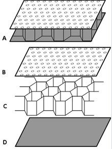
An acoustic liner is a sandwich panel made by:
- a porous top layer, called face-sheet;
- a honeycomb structure providing internal partitions;
- an impervious layer, called back-sheet or back-skin;
The lower half of a liner features dedicated internal slots to allow liquid drainage in order to prevent ice formation or fire hazards. From an acoustic perspective, this implies that the upper acoustic panel is a locally reacting liner, whereas the lower one is a non-locally reacting liner.[1]
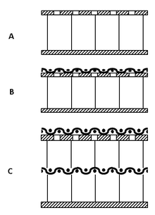
Acoustic liners can be distinguished by their internal configuration on the base of the number of honeycomb cell layers:
- Single Degree of Freedom (SDOF) liners are sandwich panels with a basic configuration, face-sheet bonded to a honeycomb layer and closed by a back-skin.
- Double Degree of Freedom (DDOF) liners are made by two layers of honeycomb cells divided by a porous septum. In particular, a DDOF liner is constituted by a top facing-sheet, a first honeycomb layer, a porous septum, a second honeycomb layer, and finally an impervious back-skin. Therefore, a DDOF liner couples two Helmholtz resonator in series.
Porous layers (e.g. the septum and the face-sheet) can be for example a perforate plate, a wire mesh or a felt-metal. The honeycomb can be of aluminum or glass fiber and the cells' size is selected small enough to ensure an acoustic plane wave in the cell for the whole frequency of interest. The face-sheet and back-skin can be either metallic or in carbon fiber. In order to have a cylindrical barrel, panel parts are structurally joined together leading to a partial loss of the acoustic area known as splice. Current state-of-the-art of acoustic are made without splices and are known as zero-splice liners. For example, the evolution of the splices width on the Airbus family ranges from three splices of about 15 cm for the Airbus A320 to a zero-splice liner for the Airbus A380.[2]
Acoustic performance
The acoustic liners' performance can be verified in dedicated experimental test rigs,[3] by means of virtual prototypes or by means of ground tests on full-scale engines.[4] Both these type of tests and simulations allow to determine the acoustic attenuation in the far-field. Moreover, the acoustic performance is linked to the acoustic impedance which can be measured with one of the following techniques:
All these methodologies measure the liner's normal impedance. However, only flow duct facilities and the in-situ method allow the measurement of the impedance in presence of the grazing flow which can affect the impedance itself.[5] Moreover, the in-situ method is the only one able to measure the impedance directly on full scale acoustic liners.[4][7]
References
- ↑ Murray, P., Ferrante, P., & Scofano, A., The Influence of Aircraft Nacelle Acoustic Panel Drainage Slots on Duct Attenuation. In 13th AIAA/CEAS Aeroacoustics Conference (28th AIAA Aeroacoustics Conference), 2007.
- ↑ Kempton, A, "Acoustic liners for modern aero-engines", 15th CEAS-ASC Workshop and 1st Scientific Workshop of X-Noise EV, 2011.
- ↑ Ferrante, P. G., Copiello, D., & Beutke, M.. Design and experimental verification of “true zero-splice” acoustic liners in the universal fan facility adaptation (UFFA) modular rig,”. In 17h AIAA/CEAS Aeroacoustics Conference, AIAA-2011-2728, Portland, OR.
- 1 2 Schuster, B., Lieber, L., & Vavalle, A., Optimization of a seamless inlet liner using an empirically validated prediction method. In 16th AIAA/CEAS Aeroacoustics Conference, Stockholm, Sweden.
- 1 2 Jones, M. G., Tracy, M. B., Watson, W. R., & Parrott, T. L., Effects of liner geometry on acoustic impedance. AIAA Paper, 2446, 2002.
- ↑ Dean, P. D.,An In-Situ Method of Wall Acoustic Impedance Measurement in Flow Duct, Journal of Sound and Vibration, No. 34 (1), 1974
- ↑ Gaeta, R. J., Mendoza, J. M., & Jones, M. G., Implementation of in-situ impedance techniques on a full scale aero-engine system. In 13th AIAA/CEAS Aeroacoustics Conference, AIAA Paper 2007 (Vol. 3441).